POSTED 01.02.17
As experts in structural integrity analysis and assessment, we’re no strangers to the mechanism known as fatigue, and the effects it can have on components. In our regular blog series our railway enthusiast Andrew Inkersole considers common fatigue mechanisms and provides a classic railway example.
As a structural engineer at EASL I encounter fatigue of metals on a regular basis and it is fair to say that if metals were not susceptible to fatigue the life of the structural engineer would generally be a lot easier. With this in mind I thought it was worthwhile reminding ourselves what fatigue is and then, with my railway hat on, discuss a practical example.
Fatigue is the structural deterioration at a localised point in a structure, typically a stress concentration, which can occur as a result of repeated stress/strain cycles caused by fluctuating loads or temperatures. After repeated cyclic loading and sufficient accumulation of localized micro-structural damage, crack initiation can occur at the most highly affected locations. The text book fatigue-related degradation mechanisms include:-
- High cycle fatigue – generally a high number of stress cycles, say more than 106, at a relatively low stress amplitude (typically below the material’s yield strength); and
- Low cycle fatigue – generally high stress range cycling with low numbers of cycles with an associated high strain range leading to plastic strains and local plasticity. The plasticity leads to more rapid material fatigue degradation.
Low cycle fatigue is generally due to the combined effects of pressure cycling, applied loads from attachments, for example piping loads, and local thermal stresses that result during both normal or faulted operation of a component.
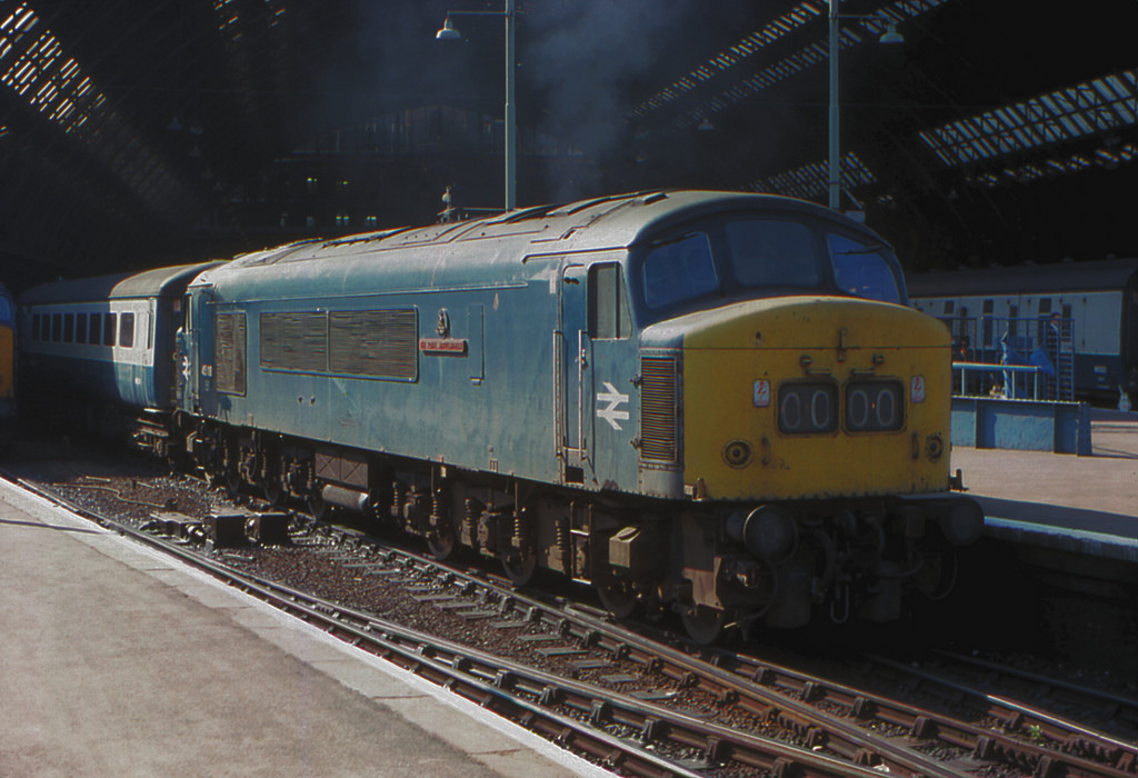
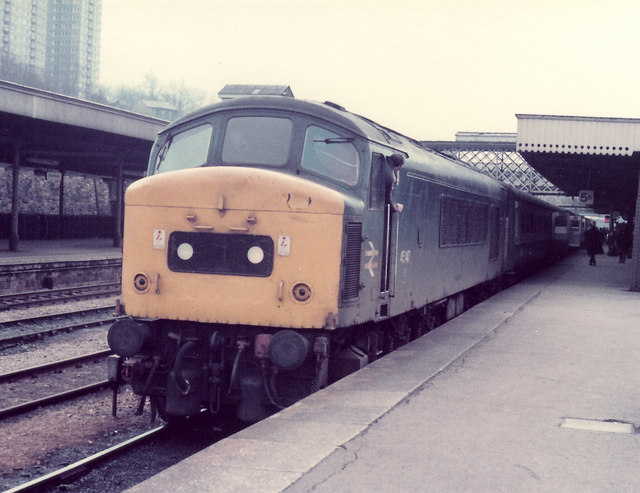
A good example of a component susceptible to high cycle fatigue is a railway axle. A railway wheelset is subject to a bending moment such that as the axle rotates a point on the axle is continually subject to tension and then compression, that is, a rotational bending stress. A ten coach train hauled by a class 45 diesel-electric has 46 wheelsets and failure of any one is almost certain to result in derailment and catastrophic consequences.
As a child, when we caught the train from Sheffield (Midland) to London St.Pancras, it would invariably be a class 45 departing platform 8 (the “far” platform adjacent to the large retaining wall for those familiar with the station). The Midland Railway milepost clearly visible from platform 8 indicates the distance as 158.5miles to London. A class 45’s driven wheel diameter is 3’ 9” which would result in approximately 71,000 revolutions to reach the buffer stops at the capital. Assuming two return journeys a day, 6 days a week, gives a total annual number of revolutions of approximately 90 million.
It is therefore important to avoid stress raisers in axles and to keep the rotational bending stress below the fatigue endurance limit of the material. However, there are many contributing factors which mean good design, alone, is insufficient. An axle may be subject to rain water, the discharge from old fashioned non-retention toilets, chemicals from the contents of a freight wagon, oils and so on which can lead to chemical attack. It may have a surface defect introduced by a thrown-up piece of ballast. Additional loads are introduced by curved railway sections and driven axles are also subject to torque from traction motors. This is why, despite good design, all wheelsets are generally subject to periodic ultrasonic inspection (a volumetric technique) and regular magnetic particle inspection (a surface technique).
The life between a reliably detectable crack size and final failure is likely to be short. Engineer’s can manage this by predicting how many cycles it would take to grow a postulated defect from the smallest size detectable by the inspection technique to an evaluated limiting defect size.
SHARE ARTICLE


Railfan: The effects of fatigue on the railway
Get in touch